|
700 Feedback Head |
700 Feedback Head |
820 Vista Vision 1 |
820 Vista Vision 3 |
|
|
|
|
|
|
|
|
|
|
|
01 |

|

|
|

|
|
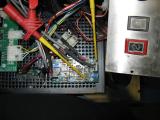
Locate the velocity board inside
the left pod |
|

|
|
Locate the kaman oscillator behind
engrave head |
|

|
|
|
Locate oscillator box & velocity board
inside the carriage |
Locate the oscillator box & the modified
velocity board inside the carriage |
Locate the oscillator box & the velocity
board behind the engrave head |
|
|
|
|
|
|
|
|
|
|
|
|
|
|
|
|
|
|
|
|
|
02 |
|
|

|
|
|
Attach voltage meter to velocity board.
Positive to 'POS' (Position) testpoint, negative to 'GND' (Ground) |
Attach voltage meter to velocity board.
Positive to 'POS' (Position) testpoint, negative to 'GND' (Ground) |
Attach voltage meter to velocity board.
Positive to 'POS' (Position) testpoint, negative to 'GND' (Ground) |
Attach voltage meter to velocity board.
Positive to 'POS' (Position) testpoint, negative to 'GND' (Ground) |
|
03 |
|
|
|
|
|
|
Voltage should be around 0 VDC |
Voltage should be around 0 VDC |
Voltage should be around 0 VDC |
Voltage should be around 0 VDC |
|
04 |
|
|

|

|
|
If necessary adjust 'zero'
potentiometer.
(Max -0.02 to + 0.02 VDC) |
If necessary adjust 'zero'
potentiometer.
(Max -0.02 to + 0.02 VDC) |
If necessary adjust 'zero'
potentiometer.
(Max -0.02 to + 0.02 VDC) |
If necessary adjust 'zero'
potentiometer.
(Max -0.02 to + 0.02 VDC) |
|
05 |
|
|
|
|
|
If the voltage is around 13 VDC the probe
is probably defective. |
If the voltage is around 13 VDC the probe
is probably defective. |
If the voltage is around 13 VDC the probe
is probably defective. |
If the voltage is around 13 VDC the probe
is probably defective. |
|
|
|
|
|
|
|
|
|
|
|
|
|
|
|
|
|
|
|
|
|
|
